Starting from this section, we will focus on analyzing the applications of various components in EMC, typically including inductors, capacitors, magnetic beads, resistors, and magnetic rings. The first is the capacitor.
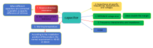
1. In EMC design, the characteristics of the aforementioned components are related to an important factor, such as frequency. Talking about capacitors, inductors, and magnetic beads without discussing frequency is meaningless.
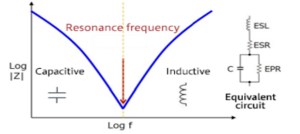
Capacitance can be understood as the series connection of parasitic inductance and capacitance. When the frequency exceeds the resonant frequency, the capacitive reactance is smaller than the inductive reactance, and the circuit gradually exhibits inductance characteristics. The resonant frequency can be calculated using the following formula.
f =1/(2π√C × ESL)
Due to the impedance characteristics of capacitors, when selecting capacitors for EMC countermeasures, it is necessary to choose based on the impedance characteristics at different frequencies:
If inductance mainly improves EMC performance by reducing di/dt, then capacitance improves EMC performance by reducing du/dt. The following figure shows how to reduce noise amplitude by adding capacitors at the output end:
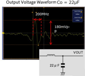
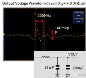
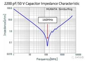
Usually, from the above figure, it can be seen that when a 2200pf capacitor is added to the output end (the resonant frequency of the 2200pf capacitor is between 100MHz-200MHz), the peak to peak value of 200MHz decreases from 180mv to 100mv. Usually, according to the summary of the EMC Foundation (II), reducing U can reduce the impact of capacitive coupling as the capacitive coupling voltage is proportional to jwUCR.
This is a method of reducing the impedance of the target noise frequency by increasing capacitance, thereby reducing the noise amplitude. In order to determine which capacitor value to choose for noise reduction processing, it is necessary to pay attention to the frequency of the signal. Here, it should be noted that the capacitance characteristics of different manufacturers also vary. When selecting capacitors, we need to pay special attention to the impedance characteristic curve of the flipped capacitor.
In order to effectively use decoupling capacitors, in addition to selecting suitable capacitors based on different frequencies, the following points should also be noted
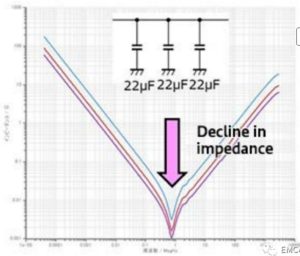
Parallel connection of multiple capacitors with the same capacitance value
When multiple capacitors with the same capacitance value are connected in parallel, the signal amplitude at that frequency can be reduced even lower
Parallel connection of multiple capacitors with different capacitance values
When noise processing is required for multiple frequency signals, multiple capacitors with different capacitance values need to be connected in parallel, but this will bring new problems, such as anti resonance points:
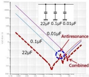
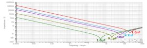
From the above figure, it can be seen that due to the inductance characteristic of 22uf after exceeding the resonance frequency, it forms a parallel resonance with a capacitor of 0.1uf. At this point, the impedance reaches the highest, indicating that the selected capacitor is selected based on the target noise reduction frequency.
2.) Reduce the impact of parasitic inductance
Due to the selection of capacitors, not only for their resonant frequency point, but also for situations where they are smaller than the resonant frequency point, it is required that the parasitic inductance of the capacitor be as small as possible. In the same situation, the smaller the package, the smaller its ESL.
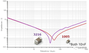
From the above figure, it can be seen that under the same capacitance value, the resonance frequency point of 3216 is ahead of the packaging of 1005, indicating that the parasitic inductance ESL of 3216 is larger.
In order to reduce the impact of capacitor ESL, capacitor manufacturers such as Murata and TDK have also developed three terminal capacitors, with the ESL part mainly connected to series circuits.
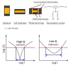
When the Q value is very high, the impedance will be very low at a specific frequency range, but when it is not within that frequency range, the impedance will rise sharply. However, capacitors with relatively small Q values can maintain a lower impedance within a certain range, which is more conducive to EMC experiments.
4.) Capacitance at different temperatures and voltages
Under high voltage and high temperature conditions, the capacitance value of ceramic capacitors will undergo significant changes. We need to pay special attention to this. When the capacitance value changes, the resonance frequency point will also change, and the filtering effect cannot be achieved.
Summary: When selecting capacitors, it is necessary to always pay attention to the following points